|
SD's DIY Hat Controller Kit |
|
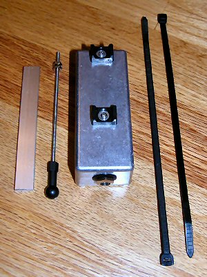 |
|
|
|
|
|
Installation
Instructions
|
|
|
|
|
|
Step 1: Detaching The Pull-Rod From The Pedal. |
|
 |
 |
|
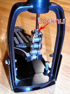
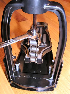
Push the pedal down to reveal the lock nut. |
With the appropriate sized wrench (10mm on the Pacific HH-820), loosen the lock nut to allow the pull rod to spin free from the chain. |
|
Step 2: Attaching The Aluminum Bar To The Pull-Rod. |
|
 |
 |
|
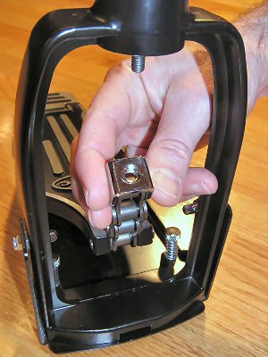
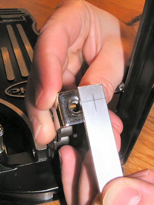
Unscrew the pull rod from the chain mounting bracket. Use the mounting hole as a guide to mark one end of the aluminum bar for drilling. |
Position the hole so that: (1) the hole will be centered from side to side of the bar, and (2) the cut end of the bar will sit flush with the front (pedal side) of the pull bar mount. |
 |
 |
|
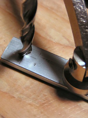
Next, center punch and drill the mounting hole. On the Pacific HH-820, the mounting hole is 1/4" in diameter. |
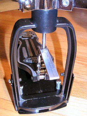
Then, insert the pull rod into the hole in the aluminum bar and spin the rod back onto the chain mount. Align the bar and temporarily secure it in place by hand tightening the lock nut -- you will have to remove the bar later to drill the second hole, so hand tightening will be sufficient. |
|
Step 3: Attaching The Sensor Assembly |
|
 |
 |
|
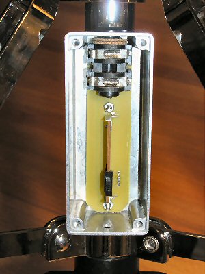
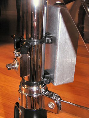
Remove the cover to the sensor assembly. Position the sensor assembly on the bottom tube of the hi-hat stand with the cover facing away from the pedal and the cable jack on the top (pointing towards the cymbal). |
Then, slide the cable ties through the slots on the black plastic mounts that are attached to the back of the sensor assembly housing. Center the box, then pull both cable ties tight and trim the excess material. |
|
Step 4: Drilling The Second Hole For The Sensor Push-Rod |
|
 |
 |
|
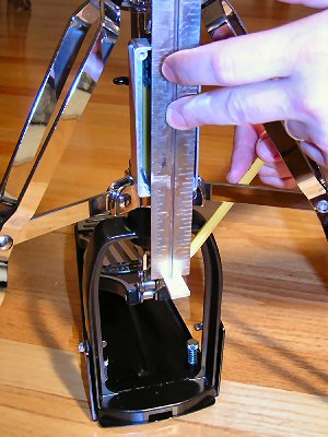
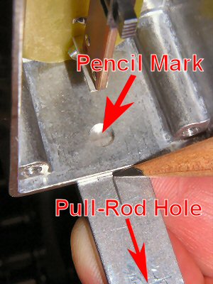
With the sensor assembly cover removed, hold a straight edge flat against the sensor opening. Let the straight edge rest on the aluminum bar that was previously fastened to the pull rod/pedal. Using a sharp pencil, mark the aluminum bar along the inside edge of the straight edge. Then, remove the aluminum bar from the pull rod. |
Hold the bar up along the bottom of the sensor housing. Place the end with the pull rod hole away from the box and the end with the pencil mark towards the box. Position the bar so that the pencil mark is centered and visible through the hole on the bottom of the sensor box. Then, make a second pencil mark on the aluminum bar along the edge of the sensor assembly housing. |
 |
 |
|
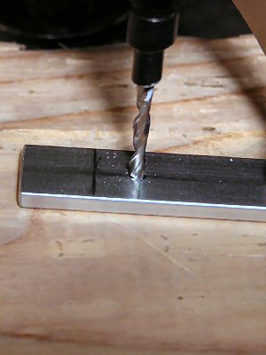
Next, center punch and drill the push rod hole at the intersection of the second pencil mark and the centerline of the bar. The hole is 7/64" in diameter. |
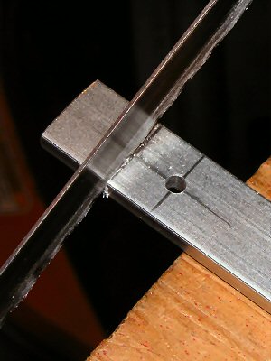
Use a hacksaw to trim the length of the bar at the first pencil mark. Smooth the cut edge with a file or sandpaper. |
|
Step 5: Attaching The Sensor Push Rod And Adjusting Travel |
|
 |
 |
|
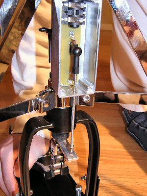
Attach the aluminum bar to the pedal/pull-rod. Align and tighten locknut. Next, remove the two nuts from the threaded end of the sensor pushrod. Slide the position sensor to the top of its travel. While depressing the pedal, insert the push rod into the hole at the bottom of the sensor housing. Attach the balljoint to the sensor and thread one of the nuts onto the end of the push rod while it hangs from the sensor. |
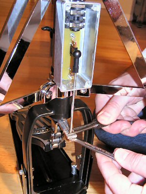
Slowly release the pedal while guiding the push rod into the hole on the aluminum bar. When the pedal reaches the top of its travel, push the sensor down about 1/16" from the top of its travel. Then, turn the nut until it just touches the aluminum bar. Thread the other nut onto the end so that the two nuts sandwich the aluminum bar. Mark the threaded rod for excess material just past the bottom nut. Remove and trim off the excess. |
 |
 |
|
Re-install the sensor push rod and secure to the aluminum bar by tightening the two nuts against each other and sandwiching the bar. Be sure to have the sensor adjusted about 1/16" short of its top position. This will provide a hard-stop to prevent damage to the sensor. The bottom of the housing provides a hard-stop at the other end of the sensor travel. |
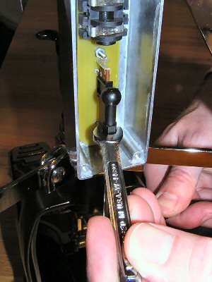
Finally, make sure that the ball joint sits flat and centered on the sensor. If it rotated while tightening, use a 1/4" open end wrench to rotate it back into alignment. |
|
|
|